Parts, Supplies and tools:

  Phillips Screwdriver
  Soldering Iron
  Electric Drill
  1/4 inch drill bit
  3/8 inch combo wrench
  Resin Core Solder
  RCA jack (Radio Shack Part No: 274-346 -- Shielded Phono Jacks)
  75 ohm resistor (68 ohm is more common and works OK)
  0.1 microfarad capacitor
  2-pin header connector (scavanged from my computer parts box)
Schematic of the mod.
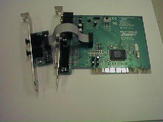
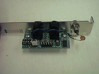
Unmodified Zoltrix with daughterboard
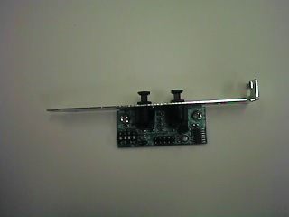
Daughterboard detail
Remove circuit board from the metal base by removing the two phillips
screws (to avoid getting metal shavings in the electornics).
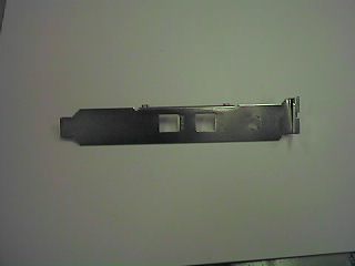
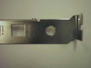
Use a 1/4 inch drill-bit to drill a hole in the metal backing
midway between the square S/PDIF OUT hole a and the top of the base.
File the hole clean and ensure that no metal shavings remain.
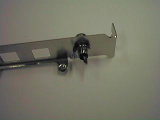
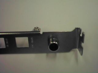
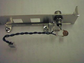
Insert the phono jack into the hole and place the contact tab and the
lock washer onto the threaded part, then thread the nut onto the jack
and tighten with the wrench.
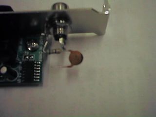
Carefully trim the leads on your resistor to fit nicely between the tabs
on the RCA jack and solder it as shown
Solder the capacitor to the center conductor lead as shown.
You don't have to have a 2 pin header connector and can solder directly
to the header pins on the board, but it is not recommended. If you
have a lot of computer junk laying around as I do, one of these should
be easy to find. These are common in generic computer cases to hook
up the power LED's and such. Once garnered, twist the wires together
(this will help avoid any electormagnetic interference that may be
present within the computer case) and carefully solder them to the
tab on the jack and to the capacitor lead.
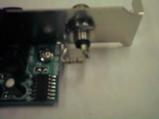
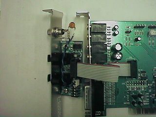
reattach the optical board to the metal base and plug the 2-pin header
plug onto the pins of J1. The lead that goes to the center pin of the
phono jack should go to pin 1 of the connection. If it doesn't work,
flip the connection and give it a try.
Ready to reinstall in the computer